Pedestal/Post - Design and Punching Shear Results
The Pedestals/Posts Design and Punching Shear Spreadsheet reports pedestal/post design information, as well as the two-way/punching shear code checks for the defined Pedestal/Post, as described in the following sections.
- This spreadsheet does not apply to beam design or individual spread footing/pedestal design.
- For detailed information on punching shear calculations, see Punching Shear - Design.
- There are no results for stem wall design or punching shear. A stem wall is only used as an analysis tool in the program.
- For additional advice on this topic, please see the RISA Tips & Tricks webpage at risa.com/post/support. Type in Search keywords: Pedestals.
Pedestals/Posts Code Checks

Click on image to enlarge it
The Pedestal Code Checks tab of the spreadsheet reports pedestal code checks and the reinforcing for the pedestals.
UC (Unity Check) and Governing LC
The UC value is the governing code check for the pedestal combined axial and bending check using the PCA Load Contour method. The Gov LC value is the load combination that resulted in the maximum code check.
Shear UC (Unity Check), Governing LC and Direction
The Shear UC value is the governing code check for the pedestal beam shear check. The Gov LC value is the load combination that resulted in the maximum code check. The Direction value is the local axis direction of the governing shear force in the pedestal.
The shear check is an envelope check. Therefore, the program will find the largest shear force (Vu) in each lateral direction and then keep track of the associated axial force (Pu) in the governing load combination(s). This means that there can be different axial forces for the check in each direction since the governing Vux and Vuz may come from different load combinations.
ACI 318-19 requires the consideration of shear interaction in y and z directions when both Vux/φVnx and Vuz/φVnz are larger than 0.5. In this case, the program recalculates the shear UC based on Equation 22.5.1.11. If the UC considering shear interaction happens to govern, this UC will be reported.
When ACI 318-19 is selected, the shear strength of concrete (Vc) uses equations in Table 22.5.5.1. Note that for members meeting the minimum shear reinforcement requirement (Av≥Av,min), Vc is taken as the larger of the results calculated by equations (a) and (b) in the table. Note that ACI 318-19 code suggests ρw may be taken as the sum of the areas of longitudinal bars located more than two-thirds of the overall member depth away from the extreme compression fiber. Therefore, RISA calculates ρw as the sum of the areas of longitudinal bars on the tension face.
When ACI 318-14 and earlier codes are selected, Vc will be taken as zero if the load combination includes a tensile axial force. Since the shear check is an envelope check, any load combination resulting in a tensile axial force will cause Vc to be taken as zero. The program will not attempt to determine if the tensile load is "significant". In ACI 318-14 Section 22.5.7.1 the language was modified but RISA still considers Vc = 0 if there is tension present.
Aside from determining if the pedestal/post is in tension or not, the shear check does not consider any axial load in the pedestal.
Phi Used
This value is based on the strain in the tension steel in the pedestal and code provisions in ACI 318-14 Section 21.2 (ACI 318-11 Section 9.3.2).
Pedestal Reinforcement
The Vertical Reinf and Shear Reinf values are reinforcement requirements for the pedestal considering spacing and reinforcement requirements per the ACI code and the Design Rules provided for pedestals. If these sections report "CUSTOM" it means that the user has applied a custom rebar layout.
Punching Shear Values

Click on image to enlarge it
The Punching Shear Values tab of the spreadsheet reports the basic / summary data for the punching shear code check.
UC (Unity Check) and Governing LC
The UC value is the governing code check (Total Stress /phi*Vnx) for the pedestal punching shear. The Gov LC value is the Load combination that resulted in this maximum code check.
Location
The pedestal and slab geometry is investigated and checked for all three types of punching failure (Interior, Edge and Corner). This field represents the type of failure method that controlled the code check calculation for the given pedestal. For more information on how this works, see Punching Shear - Design.
Vuy
This value represents the factored load transferred from the pedestal into the slab for the governing load combination. This value corresponds to the axial force in the Pedestal/Post after subtracting the counteracting bearing pressure force that occurs within the punching shear perimeter.
Muz and Mux
These values represent the factored moments about the local axes of the Pedestal/Post.
Total Stress
The Total Stress is the direct shear stress plus the shear stress due to moment. For more information, see Punching Shear - Design.
Phi*Vny
This represents the shear stress capacity of the slab calculated based on the three ACI equations for two-way or punching shear capacity of the slab. For more information, refer to ACI 318-14 Section 22.6.5 (ACI 318-11 Section 11.11.7.2). When ACI 318-19 is selected, the shear strength of concrete (Vc) uses equations in Table 22.6.5.2. Note that an additional size effect factor λs is added in the equation. λs is a function of effective depth of the slab 'd', and is calculated per Equation (22.5.5.1.3).
- This value does NOT include any additional capacity due to shear reinforcing in the slab.
- For CSA A23.3-04 code provision 13.3.4.3 is used.
- For Eurocode2 : BS EN 1992-1-1:2004+A1:2014 code section 6.4.4 is used.
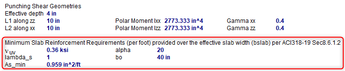
Minimum Slab Reinforcement at Punching Shear Critical Section
ACI 318-19 requires a minimum slab reinforcement at punching shear critical section if vuv>φ2λφ√f’c per Section 8.6.1.2. As,min is calculated and presented in the punching shear result of columns under this condition. Please note that the reinforcement design in elevated slabs does not consider this requirement, users need to adjust the slab reinforcement at punching shear critical sections to account for this code requirement. RISA provides the calculations of As,min per Equation (8.6.1.2) in the Detail Report - Punching Shear Results. Please note that the As,min calculated is based on area of steel per foot, i.e., b_slab was taken as 12”. The calculated As,min shall be multiplied by b_slab (specified in 8.4.2.2.3) to obtain the total area of steel required.
Click on image to enlarge it
Punching Shear Geometries

Click on image to enlarge it
The Punching Shear Geometries tab of the spreadsheet reports the basic geometry data used for the punching shear code check.
Shape
The Shape column shows the pedestal/post shape description assigned at the corresponding node location.
Location
The pedestal and slab geometry is investigated and checked for all three types of punching failure (Interior, Edge and Corner). This field represents the type of failure method that controlled the code check calculation for the given pedestal. For more information on how this works, see Punching Shear - Design.
Effective Depth
The effective depth of the slab is used to define the punching shear perimeter at a distance of d/2 beyond the edge of the pedestal.
L1 and L2
The L1 and L2 variables represent the length of the critical section along the local axes.
Polar Moment - xx and Polar Moment - zz
This is a property (Jc) of the critical section, which is analogous to polar moment of inertia about the longitudinal column/pedestal axes.
Gamma x and Gamma z
This value is calculated from the dimensions of the assumed punching shear perimeter. It represents the fraction of the unbalanced moment for each axis that is transferred by eccentricity of shear.
Pedestal/Post Detail Report
The Detail Reports for pedestals/posts show the overall geometry, materials, codes and analysis/design values used in coming up with the reinforcing and code check values. Below, we will walk through each section of the report.
Input Data and Graphics

Click on image to enlarge it
The Input Data section lists the point label of the pedestal/post, material properties, reinforcement properties and design requirements, as applicable. The graphics in this section show a plan and section view of the geometry for the pedestal/post along with the actual pedestal reinforcement designed by the program.
Design Checks

Click on image to enlarge it
The Shear Check Results summarize the shear capacities and demands along with the shear ties considered. The Vc values are the shear capacities of concrete only in each of the horizontal directions. The Vs values are the shear reinforcement capacities in each of the horizontal directions. The Vu values are the demand requirements in each of the horizontal directions. The code check value comes from the equation below:
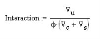
The Gov LC value is the load combination that results in the governing code check, based on the highest shear force. The shear check is an envelope check. Therefore, the program will find the largest shear force (Vu) in each lateral direction and then keeps track of the associated axial force (Pu) in the governing load combination(s). This means that there can be different axial forces for the check in each direction since the governing Vux and Vuz may come from different load combinations.
When ACI 318-19 is selected, the shear strength of concrete (Vc) uses equations in Table 22.5.5.1. Note that for members meeting the minimum shear reinforcement requirement (Av≥Av,min), Vc is taken as the larger of the results calculated by the equations (a) and (b) in the table. Note that ACI 318-19 code suggests ρw may be taken as the sum of the areas of longitudinal bars located more than two-thirds of the overall member depth away from the extreme compression fiber. Therefore, RISA calculates ρw as the sum of the areas of longitudinal bars on the tension face.
When other ACI 318 editions are selected, the shear strength of the concrete alone is limited to the standard 2*λ*sqrt (f'c) equation from ACI 318-14 Section 22.5.5.1 (ACI 318-11 Section 11.2.1.1) and does not use the more detailed calculations of ACI 318-14 Table 22.5.5.1 (ACI 318-11 Section 11.2.2). Per ACI 318-11 section 11.2.1.3, Vc will be taken as zero if the load combination includes a tensile axial force. Since the shear check is an envelope check, any load combination resulting in a tensile axial force will cause Vc to be taken as zero. The program will not attempt to determine if the tensile load is "significant". In ACI 318-14 Section 22.5.7.1 the language was modified but RISA still considers Vc = 0 if there is tension present.

Click on image to enlarge it
Aside from determining if the pedestal/post is in tension or not, the shear check does not consider any axial load in the pedestal.
The Bending Check Results summarize the moment capacities and demands along with the longitudinal reinforcing considered. The Pu and Mu values are the axial and moment demand requirements. The Pn and Mn values are the axial and moment capacities based on the PCA Load Contour method. The Mnox and Mnoz are the uniaxial moment capacities. For more information on this method, see the Notes on the ACI 318 Building Code Requirements for Structural Concrete, a document provided by the PCA. The Parme Beta factor defaults to 0.65. The Gov LC is the load combination that produced the maximum unity check. The Long. Bars and the % Steel give the actual amount of steel and the number of bars in the pedestal. The Unity Check is a combined axial and bending unity check based on the interaction diagram for the pedestal.
The Compression Development Length section gives the values for longitudinal bar compression development length checks. The required length is the compression development length required per the ACI 318 code. The available length is the actual maximum value considering the thickness of slab and the bottom cover requirements. The equation for determining the available length is:
Lavailable = concrete thickness – cover – 2*reinforcing bar diameters – dowel bar diameter
The program uses a default value of the diameter of a #5 bar as the footing bar diameter for this calculation (0.625 in).
Lrequired/Lavailable gives the code check ratio.
Punching Shear Check Results

Click on image to enlarge it
The Unity Check gives a ratio of demand to capacity, while the Gov LC gives the load combination that produced this maximum unity check.
For an explanation of the rest of these values see both the spreadsheet result explanations above, as well as the Punching Shear - Design topic.